I have an XML layout from an older application that contains coordinates for the shapes and connecting lines. I’ve made a C# script that translates this XML layout into a BPMN layout. The result is below
<?xml version="1.0" encoding="UTF-8"?>
<bpmn2:definitions xmlns:xsi="http://www.w3.org/2001/XMLSchema-instance" xmlns:bpmn2="http://www.omg.org/spec/BPMN/20100524/MODEL" xmlns:bpmndi="http://www.omg.org/spec/BPMN/20100524/DI" xmlns:bioc="http://bpmn.io/schema/bpmn/biocolor/1.0" xmlns:color="http://www.omg.org/spec/BPMN/non-normative/color/1.0" xmlns:di="http://www.omg.org/spec/DD/20100524/DI" xmlns:dc="http://www.omg.org/spec/DD/20100524/DC" xmlns:Custom="http://somsite.com/Custom" xmlns:platform="http://platform/schema/bpmn/platform" id="Definitions_Process_37" targetNamespace="http://activiti.org/bpmn" exporter="bpmn-js (https://demo.bpmn.io)" exporterVersion="9.0.0-alpha.2">
  <bpmn2:process id="Process_37">
    <bpmn2:intermediateThrowEvent id="Action_273612917" name="ActionName" Custom:ActionId="79">
      <bpmn2:outgoing>FlowEndpoint_161</bpmn2:outgoing>
    </bpmn2:intermediateThrowEvent>
    <bpmn2:sequenceFlow id="FlowEndpoint_161" sourceRef="Action_273612917" targetRef="Status_140" Custom:TransitionId="161" Custom:TransitionStartId="109" Custom:IsActive="True" Custom:IsEndPoint="true" />
    <bpmn2:task id="Status_140" name="StatusName" Custom:StatusId="140">
      <bpmn2:incoming>FlowEndpoint_161</bpmn2:incoming>
    </bpmn2:task>
  </bpmn2:process>
  <bpmndi:BPMNDiagram id="BPMNDiagram_Process_37">
    <bpmndi:BPMNPlane id="BPMNPlane_37" bpmnElement="Process_37">
      <bpmndi:BPMNEdge id="FlowEndpoint_161_di" bpmnElement="FlowEndpoint_161" bioc:stroke="#000000" color:border-color="#000000">
        <di:waypoint x="209" y="211" />
        <di:waypoint x="443" y="110" />
      </bpmndi:BPMNEdge>
      <bpmndi:BPMNShape id="Action_273612917_di" bpmnElement="Action_273612917" bioc:stroke="#000000" color:border-color="#000000">
        <dc:Bounds x="175" y="184" width="36" height="36" />
        <bpmndi:BPMNLabel>
          <dc:Bounds x="153" y="220" width="81" height="27" />
        </bpmndi:BPMNLabel>
      </bpmndi:BPMNShape>
      <bpmndi:BPMNShape id="Status_140_di" bpmnElement="Status_140">
        <dc:Bounds x="443" y="90" width="154" height="40" />
      </bpmndi:BPMNShape>
    </bpmndi:BPMNPlane>
  </bpmndi:BPMNDiagram>
</bpmn2:definitions>
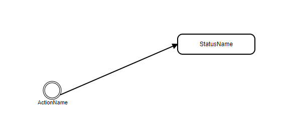
Everything is ok, if I load it into BPMN it does so without any error, like in the picture below.
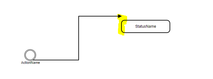
My issue is the following: When I try to move the task shape (StatusName) , the connection line “snaps” outside the shape, like in the picture below.
I’ve downloaded the layout generated by the BPMN website and, except some coordinates changes, I could not find anything different. The connection ends where shape starts, both in my layout and the BPMN layout. If I place the connection manually on BPMN canvas, it won’t snap out of place again.
I’ve tried setting some offsets (200 units for X-axis, and 100 units for Y-axis) on my layout, but it didn’t help.
Does anyone have any idea what is causing this issue?
Thanks,
Saby